The working from the DCF77 signal
DCF77: Deutschland (Germany), C as sign that it concerns a long wave transmitter,
Frankfurt 77,5kHz.
 DCF77 is a timesignal and is transmitted on 77,5kHz as coded time information.
The power of the long wave transmitter is 50kW with a radius of ca.2000km around Mainflingen (25km from Frankfurt, Germany).
The transmission from the signal over the long wave is very efficient because the range is extremely high (almost entire Europe),
reflections in the ionosphere
can be neglected and the signal reception is also good within buildings.
Ofcourse it has also it's disadvantage, it will take almost a minute to transmit time and date complete.
The DCF77 signal (and it's carrier) is generated by the PTB (Physikalisch Technische Bundesanstalt)
with atomclocks in a building in Mainflingen (the control is situated in Braunschweig)
with a precision better than 1 second over 300,000 years and send out from there.
Reception is possible, exceptions as thunderstorms in the area leaving aside, 24 hours a day (since 31 August 1970).
By servicing would be switched over to reserve antennas.
The transmitted time information is the CET (Central European Time) and DST (Daylight Savings Time) is also added in summer.
|
|
 Relative simple, cheap receivers can receive this long wave.
Watches, clock radio's and clocks which work with the DCF77 signal give the exact date and
time till the last second.
The protocol used to transmit time data is quite simple:
every minute the full time and date are transmitted in 59 bit (from 0 to 58).
At the beginning of every second a bit is transmitted by reducing the 77.5kHz carrier to 25% (-6dB)
for a while (a sort of digital amplitude modulation).
If the power stays low for 100 mSec (0,1 sec) the transmitted bit is '0' and
if the power stays low for 200 mSec (0,2 sec) it's '1'.
The 60th bit (number 59) is not transmitted,
this is used as a marker to detect the beginning of each minute (and each group of 59 bit).
|
 |
|

|
Orderno. 64 11 38
Conrad supplies a ready made DCF77 receiver |
|
Orderno. 53 60 08
Also is an individual DCF77 ferriet-antenna available |
With the DCF77 projects from this website the DCF77 module from Conrad orderno.
64 11 38 is used.
Be aware that the DCF77 module (receiver) must have a distance from a working computer to avoid interference,
that means also a distance from minimal 1 metre from the PIC.
Also TL's, lightdimmers and microwave can make lots of trouble from the DCF77 reception, so keep the antenna away from there.
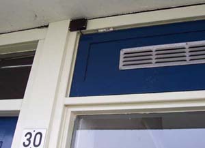
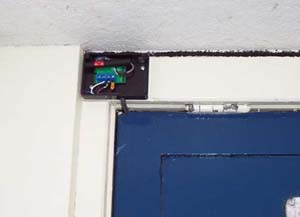
The best result is to place the entire DCF77 module outside the house (see photo's).
 |
 |
|
The best remedy for optimal reception is to place the DCF77 module including the antenna in a small
synthetic (no metal!) box and place this outside the house.
|
A shielded cable isn't necessary, but place on the side from the DCF77 module a serial resistor from 100 Ω and
after that a (tantalium) capacitor from 4µ7 over the power supply (see scheme's).
The (unshielded) cable between the DCF77 module and the PIC inside my home is 10 metres and works unproblematic.
Take if it's possible a cable with 4 conductors, the DCF77 module needs only 3 but the fourth conductor is used in another project.
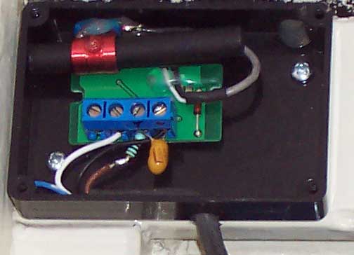 |
There are two outputs on the DCF77 module, the right one is direct,
the left one is inverted, take the direct one next to the +.
The 4th conductor (blue) is for an other new project. |
PIC program
DCF77 is pretty simple.
Every second there comes a pulse from the DCF77 module.
For a 0 is the pulsewidth 0.1 second and for a 1 is this 0.2 second.
Thus:
Measure till a pulse comes in.
Then a delay from 0.15 second.
Then measure again.
Is the pulse already gone then you've received a 0 and if the pulse is still there it is a 1.
The program in the PIC expect every second a '0' or '1', so if there is after a second nothing received,
the PIC knows that the next second, must be second 00 from a new minute.
The value from the second is not transmitted,
to make a time-indication with seconds the PIC-program must have a counter which counts-up every time
when a bit is received and display it on a time-indication (LCD or LED-display),
and if one second nothing is received (second 59) must there be '59' displayed on the time-indication.
All values are transmitted (since 1973) in BCD code, more info about BCD.
Paritybits
It is recommended to make in every PIC program use from the three DCF77
paritybits, the programs from this website do.
There is a paritybit for the minutes, the hours and for the date.
DCF77 works with even parity, this works as follows:
The hours for example have 6 bits plus a paritybit (see bitgraduation in the
minute underneath).
The bits which are 1, are add up inclusive the paritybit, the result must be an even
number.
If there is a bit wrong received, a 0 is as 1, or a 1 is as 0 received, then the result is
uneven.
Suppose it is 8 o'clock in the morning, the 6 bit hour bittrain is then 00 1000 (= 08,
BCD).
Because there is only 1 bit high,
is the paritybit for the hours which is transmitted direct after it also a 1 to come to an even
number.
If the result is uneven (parityerror) the PIC place the wrong received time or date not on the LCD.
Instead of this the PIC must calculate the actual time from out the previous time by hisself and place
thís on the LCD.
In case of a parityerror:
- Increase the present minute with 1
- Becomes minute greater than 59 then minute = 0 and increase also the hour with
1
- Becomes hour greater than 23 then hour = 0
To increase also the date that makes no much sense, but it is important that
if there is a parityerror, not making the date from that minute equal to
the received DCF77 date but skip the date updating so that the date from the
previous minute is displayed.
The chance that there is a parityerror at midnight (00:00) is very small and íf
it happens then the date is updated the minute after (at 00:01).
In the beginning I let count the PIC the parityerrors and it seems that a parityerror happens 5 till 10 times a
day.
But the error recovery makes that I've never had a wrong time and date anymore here at home.
 |
| Bit |
Name |
Description |
Comment |
| 0...14 |
- |
Reserved |
Coding to requirement |
| 15 |
R |
Send antenna |
0 = Standard antenna / 1 = Reserve antenna |
| 16 |
A1 |
Announcement 1 |
1 = Next hour a Daylight Saving Time (DST) change occurs |
| 17 |
Z1 |
Time Zone bit 1 |
0 = Winter / 1 = Summer (DST) |
| 18 |
Z2 |
Time Zone bit 2 |
0 = Summer / 1 = Winter (usually the opposite of Z1) |
| 19 |
A2 |
Announcement 2 |
1 = Next hour an extra second is inserted (leap-second) |
| 20 |
S |
Startbit |
Always 1, startbit coded time information |
| 21...27 |
|
Minutes |
7 bit, BCD, LSB first (00...59) |
| 28 |
P1 |
Parity bit 1 |
Even parity for all received bits from the minutes |
| 29...34 |
|
Hours |
6 bit, BCD, LSB first (00...23) |
| 35 |
P2 |
Parity bit 2 |
Even parity for all received bits from the hours |
| 36...41 |
|
Day of the month |
6 bit, BCD, LSB first (01...31) |
| 42...44 |
|
Day of the week |
3 bit, BCD, LSB first (1 = Monday...7 = Sunday) |
| 45...49 |
|
Month |
5 bit, BCD, LSB first (01...12) |
| 50...57 |
|
Year |
8 bit, BCD, LSB first (00...99) |
| 58 |
P3 |
Parity bit 3 |
Even parity for all received bits from the date |
A1: Announcement that next hour a Daylight Saving Time (DST) change occurs, signal is '1' for one hour before changing.
This can be used to stop analog clocks for one hour when the (analog) clock must set one hour back.
A2: Announcement that next hour a leap second is inserted, this is nessecary once in the few years.
Since 1972 is this leap second inserted once in a while.
Second 60 is without bit transmission inserted (just like second 59).
Probably this happend for the last time at 1 January 2006.
Experts will do a timeadjust when there is a leap minute, because timeadjustments are difficult for managers from computernetworks.