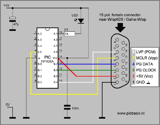
Connect the Wisp628/648 or Galva-Wisp PIC programmer with the marked pins from the choosen PIC device.
| 15 pins bus from Wisp programmer | connections from PIC | recommended wire color | 8-pin PICmicro's | 14-pin PICmicro's | 18-pin PICmicro's | 28-pin PICmicro's | 40-pin PICmicro's |
| 12F629 12F675 | 16F630 16F676 | 16C84 16F84(A) 16F627 16F628A 16F648A | 16F73 16F76 16F870 16F872 16F873 16F873A 16F876 16F876A 18F242 18F248 18F252 18F258 | 16F74 16F77 16F871 16F874 16F874A 16F877 18F442 18F448 18F452 18F458 | |||
| 1 | Gnd (ground, VSS) |
black | 8 | 14 | 5 | 8, 19 | 12, 31 |
| 2 | Vcc (power, VDD) |
red | 1 | 1 | 14 | 20 | 11, 32 |
| 3 | PG Clock | green | 6 | 12 | 12 | 27 | 39 |
| 4 | PG Data | blue | 7 | 13 | 13 | 28 | 40 |
| 5 | MCLR | yellow | 4 | 4 | 4 | 1 | 1 |
| 6 | LVP (PGM) | white | - | - | 10 | 24 | 36 |
The yellow MCLR wire carries the 13V program voltage.
Example with a PIC16F628A:
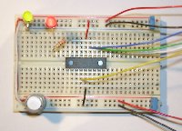
You should not mistake one wire for another, seen that changing wires can damage the target PIC.
It is recommended to use the given wire colors with experiments on breadboard, etc. (= Wisp standard).
![]() For programming small PIC's you need an extra (small) circuit
For programming small PIC's you need an extra (small) circuit
ICSP: In Circuit Serial Programming
The PIC can stay in his circuit while it is gonna be programmed.
So a builded circuit around a PIC which steers the components (display, LED's, switches, etc.) can still connect to the PIC when it is in programming mode,
when the next rules are followed:
|
|
Normally PORTB.6 and PORTB.7 are normal in/outputs, but are also used when the PIC is gonna be programmed. While the PIC is programmed also the parts (components) which are connected with those two ports get these signals from the PIC programmer. If PORTB.6 and/or PORTB.7 is set as input then the connected component on this port (i.e. a switch or optocoupler) may not give any signal. A relay shall switch on and off very rapidly and a LED blinks very fast. A LED that blinks fast doesn't matter, but a relay (for example) maybe does (depence on the builded situation). Recommended in a situation like this is to choose another PIC port for the relay. A connected component on these ports may take a maximum current about 10mA, because else the PIC programmer can't deliver the signals from enough voltage. A display which is connected to these ports (default from PIC Basic) can stay while the PIC is gonna programmed,
only while programming the display shows "strange" characters on his screen, but it doesn't damage the display. |
||
|
|
The MCLR pin from the PIC carries while programming the PIC a programvoltage from 13 volt ! A component which is connected with this port and normally gives a signal to this input, must suffer this voltage and may not give an active signal while the programmer programs the PIC. (This pin can't set as an output on the PIC). |
||
|
|
For the PGM pin the same story as for PORTB.6 and PORTB.7 (see hereabove). (Some PIC devices doesn't have a PGM connection, see table). |
It is to be recommended to decide first, which applied components must connected to which PIC port in a new project, before a PCB is developed, with an eye to in circuit programming (ICSP).
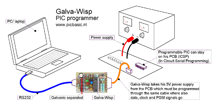 |
| The (temporary) connection (orange cable on the drawed picture) between the PIC programmer and the PCB which contains the PIC, can made by a 6-pole connector (own choise, own standard) which is connected by the PCB to the program pins from the PIC. |
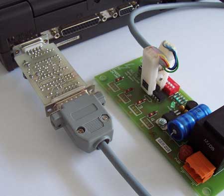 |
| Another solution is to place a DIL-clip over the PIC. If the PIC has been programmed then the clip can removed. (On the picture is a 16F630 programmed. This chip has no white wire (PGM) connection). |