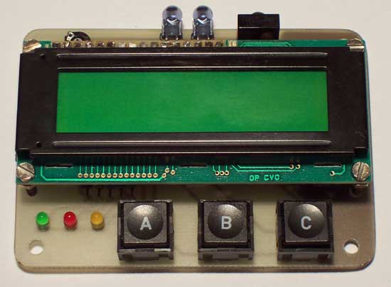
The universal RC5/RC6 transceiver.
This project is an expansion from another project from this website.
On the one side you can read the RC5, RC5X and RC6 codes from remote controls on a LCD and on the other hand
you can send all thinkable RC5, RC5X and RC6 codes to a device.
Besides is for this project a PCB layout drawed to make it still more easier for you.

The universal RC5/RC6 transceiver.
The IR receiver:
When the TSOP1736 (IR receiver) receives an infrared (IR) signal from a RC5 or RC6 remote control
(like Philips) burns LED1 (green).
The LCD shows when it receives a new type of code for one second which protocol is received
(RC5, RC5X or RC6).
After then the LCD shows the RC5 or RC6 system- and command code in decimal as wel in binair.
The toggle-value is shown by LED3 (yellow).
LED2 (red) burns if the received signal is poor or if it's not a RC5, RC5X or RC6 signal.
If you only want to know the code from a button then you can ofcourse also look at the RC5 tables from
this website (See here and here).
The IR transmitter:
With the IR-transmitter it is possible to send every possible code from the RC5, RC5X and RC6 protocol,
like a remote control does.
With the help of the LCD you can adjust which RC5, RC5X or RC6 system- and command code must send out.
When start up select first with 'ADJUST' (S2) the RC5 or RC6 protocol, when the choise is right, confirm with 'SEND' (S3).
To adjust the command value press 'ADJUST'.
If this button is pressed for a longer time, the counter changes from direction.
If this button is pressed much longer, then the counter starts repeating automatically and counts faster and faster.
When PORTA.5 is connected to GND (keep S1 pressed), then changes not the command value,
but the RC5 or RC6 system-address, the system-address will be stored in EEPROM.
The in this way adjusted code will be transmitted, by pressing 'SEND' (S3).
If 'ADJUST' and 'SEND' are pressed both, the program restarts, then you can select between RC5 and RC6 again.
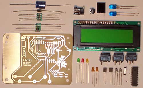
The components.
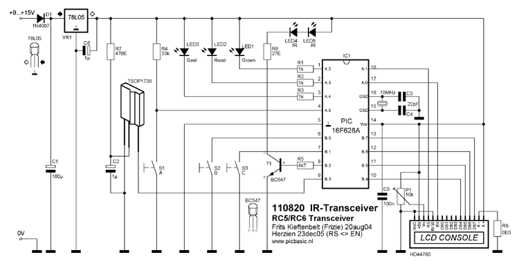
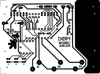
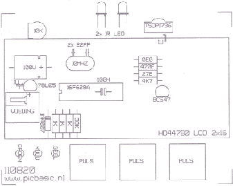
| PCB | PCB 110820 (or etch it by yourself ofcourse) |
| LCD | HD44780 (or compatible) 2x16 characters |
| IC1 | PIC16F628(A) |
| VR1 | 78L05 voltageregulator |
| IR receiver | TSOP1736 |
| LED1,LED2,LED3 | Green, red and yellow LED, Ø3mm |
| LED4,LED5 | Infrared (IR) LED, Ø5mm (i.e. LD274) |
| T1 | BC547 NPN transistor |
| D1 | 1N4007 diode |
| X1 | Crystal 10MHz (if possible a low type) |
| R1...R3 | 1k |
| R4 | 33k |
| R5 | 4k7 |
| R6 | 27Ω |
| R7 | 470Ω |
| R8 | 0,0Ω (or just a wire) or resistor for LCD backlight (see text) |
| P1 | Potmeter 10k...47k, 6mm |
| C1 | 100µF |
| C2, C6 | 1µF (tantalium) |
| C3, C4 | 22pF |
| C5 | 100n...220n, SMD (or axial) (comes under IC1, solderside) |
| S1,S2,S3 | Make contact pulser |
| Conn1 | Voedingsconnector 3,5mm |
| IC-socket | Own choise |
Tips for building:
This is a lowcost project, when a HD44780 2x16 LC-Display is already there.
If you're going to build this project, read also the other two projects for more clearness:
| Display RC5/RC6 codes on a LCD | |
| What is RC5? |
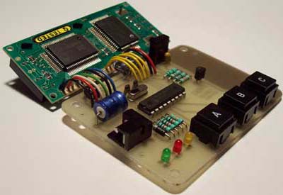
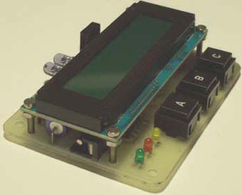
|
|
Use flexible wires to connect the LCD because the LCD must turn away when the PIC must reprogrammed for updates (ICSP). Massive wires will break after bending a couple of times.
|
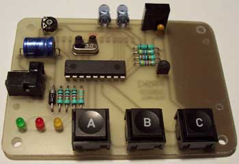 |
This prototype hasn't a 78L05 supply-stabilizer yet, the original PCB does. |
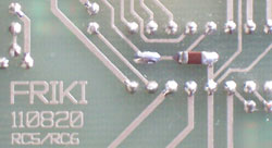 |
The PIC have his capacitor in SMD package,
so this have to be soldered on the solderside under the PIC. |
When switch on, the green LED must blink and according to the LCD you must make a choise between RC5 and RC6 first.
When the LCD doesn't do a thing at all then probably is P1 not good adjusted.
With P1 you can adjust the contrast from the LCD.
The binary notation has in version 2 (V-2) leading zero's.
Display V-1: 101 (old notation)
Display V-2: 00000101
Version 3 (V-3) has an improved control and stores the latest adjustments in his EEPROM.
These latest adjustments should send at least one time before it is stored (push 'SEND' button).
Version 4 (V-4) shows the binary system value in RC5X mode correct (previous versions shows only 6-bits instead of 7).
The HEX file is now set for a 16F628A instead of 16F628.