The Galva-Wisp PIC programmer
The Wisp628 from www.voti.nl
is an In Circuit Serial Programmer to program a flash PIC which mostly can stay in your circuit.
No irritating doings like pulling the PIC out of the PCB, place it in the programmer,
programming it, pull it out the programmer and place it back in the PCB, over and over again,
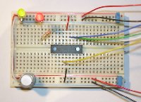
it can stay in your breadboard or PCB while programming the PIC.
It becomes risky when the PIC is connected direct to 230V main,
like the wireless controlled (and trafo-less!) dimmer from this site,
then it's better to program the PIC separate from the circuit.
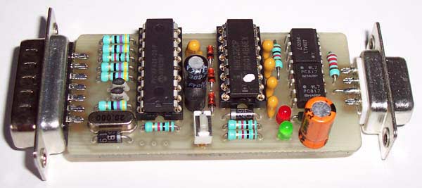
The Galva-Wisp PIC programmer
Galva-Wisp
Another solution to protect your PC is to isolate the Wisp628 programmer galvanic from the PC (see schematic diagram underneath) or
to build the Galva-Wisp, that's the Wisp628 but galvanic separated by 2 dual-optocouplers.
The Galva-Wisp is expanded with a green power on LED, a red program LED and a pushbutton for the possibility to reset the programmed PIC manual.
By the way, the manual reset is only possible when MCLR is enabled. (CONFIG MCLRE_ON in PIC-Basic (=default))
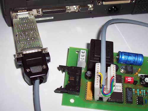
Here the Galva-Wisp PIC programmer is connected direct into the COM-port from a PC.
Ofcourse you can use a (1:1) cable between the COM-port and the programmer.
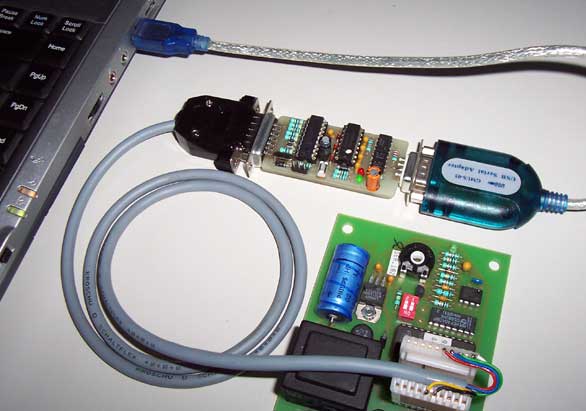
If no COM port is present, then use an USB-serial adapter.
 |
 |
|
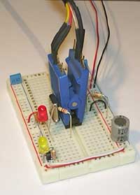
To connect the programmer with the PIC which must be programmed you can do it with wires but it is more easy when using a DIL-clip. Programming the PIC is then also possible when the PIC is already soldered into a PCB (see pictures above this one). |
Further is the Galva-Wisp the same as the Wisp628, it can program till now the next PIC-types:
| 12F629, 12F675 | |
| 16F630, 16F676 | |
| 16F83, 16C84, 16F84(A) | |
| 16F627(A), 16F628(A), 16F648A | |
| 16F818, 16F819 | |
| 16F72, 16F73, 16F74, 16F76, 16F77 | |
| 16F737, 16F747, 16F767, 16F777 | |
| 16F870, 16F871, 16F872, 16F873(A), 16F874(A), 16F876(A), 16F877(A) | |
| 16F87, 16F88 | |
| 18F242, 18F2439, 18F248, 18F252, 18F2539, 18F258, 18F442, 18F448, 18F452, 18F458 | |
| 18F1220, 18F1320, 18F2220, 18F2320, 18F4220, 18F4320, 18F4439, 18F4539 | |
| 18F6520, 18F6525, 18F6585, 18F6620, 18F6720 | |
| 18F8520, 18F8525, 18F8585, 18F8620, 18F8621, 18F8680, 18F8720 |
Notes:
- Writing ID memory is not supported for 16F7x.
- Chips that are shown in grey are supported conform Microchip's programming specifications, but have not been tested with a real chip.
- Although not explicitly mentioned the LF (low power) variants of the mentioned chips are also supported.
- Programming chips that can configure their /MCLR pin as input can (especially when this feature is used) requires an
additional circuit.
![]() Summary PIC's programmable by Galva-WISP / WISP628
Summary PIC's programmable by Galva-WISP / WISP628
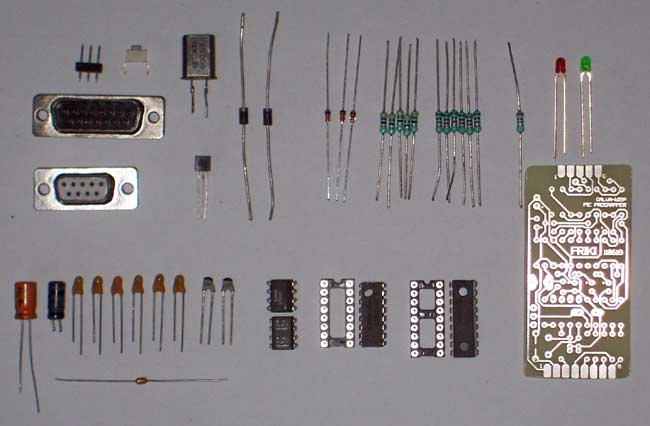
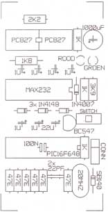
The components: the 3-pins header and the reset push-button can leave if not used.
| PCB | PCB 110618 or etch it by yourself (31mm x 64mm) |
| IC1 | PIC16F648A (download program from www.voti.nl) |
| IC2 | MAX232 (or HIN232) |
| IC3,IC4 | PC827 (or LTV827) (dual optocouplers) |
| LED1,LED2 | Red and green LED, Ø3mm, 2mA low current type |
| T1 | BC547 NPN transistor |
| -see text | TIP120 NPN darlington transistor (see text) |
| D1 | 1N4007 diode |
| D2,D3,D4 | 1N4148 diode |
| D5 | SB140 Schottky diode |
| X1 | Crystal 20MHz |
| R1,R2,R11 | 1k |
| R3...R8 | 47Ω |
| R9 | 3k9 |
| R10 | 2k2 |
| R12 | 1k8 |
| C1...C4,C6,C7 | 1µF (tantalium) |
| C5 | 1000µF / 6,3V or 10V (radial) (see text) |
| C8 | 22µF |
| C9,C10 | 22pF |
| C11 | 100n, axial (comes under IC1, in the IC socket) |
| S1 | Reset push-button (may left away) |
| Conn1 | 15-pole sub-D connector, male |
| Conn2 | 9-pole sub-D connector, female |
| IC-sockets | Own choice |
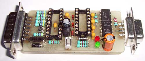
C11 is mounted on the inside of the IC socket under the PIC.
Pay attention for the wire connected on pin 7 from the 9-pole sub-D connector
Beware that the 2 optocouplers (IC3 and IC4) are mounted with the indentation to each other.
The diode D5 must be a Schottky diode, for example type SB140.
C11 is mounted in the IC-socket under the PIC.
The PIC must placed anyhow in a socket so that these from time to time can be replaced with new software
so that the newest PIC types can be programmed.
Updating is possible by programming the update in another 16F648 first and then replace the PIC (IC1) with it.
You can re-program the 'old' PIC for another project.
The Galva-Wisp takes his power from the target PIC circuit (where the PIC stays which has to be programmed)
(5V/25mA) and the RS232 COM-port (+/- 9V...12V).
Additional circuit
Some PIC's (like 12Fxxx and 16F630/16F676) can configure their /MCLR pin as input.
These chips will (in most cases) fail to get into programmingmode when the /MCLR pin is indeed configured as input.
 Giving Vpp a fraction before the power from the target PIC is active solve this problem.
The Galva-Wisp shorts the target PIC's power very briefly (a few milliseconds), while the /MCLR pin goes to Vpp.
Schottky diode D5 and big capacitor C5 (1000µF) ensures that the Galva-Wisp still has power during this brief period.
It's important that the 2 LED's are a low current type, else capacitor C5 is to small.
The LED's burn with resistors R9 (3k9) and R10 (1k8) not very bright, because of currentsaving when programming.
In any case the power to the target PIC must tolerate this brief short,
it must not deliver more current than the TIP120 darlington transistor can handle (a few ampère) and it must recover fast.
A 7805 or 78L05 based power supply will do fine, some lab power supplies will not,
because they are designed to 'fold back' after an overcurrent situation and recover slowly.
In such cases a 10Ω resistor in series with the power supply might solve the problem.
Note: Choose a radial low-voltage (6,3V or 10V) capacitor for C5 else it doesn't fit on the Galva-Wisp PCB.
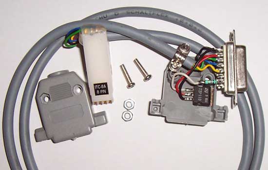
The TIP120 is not placed on the Galva-Wisp PCB board but must mounted in the 15-pole sub-D connector.
Cut the upper metal part from the TIP120, then it will better fit in the connectorhouse.
The TIP120 is connected between pin 1 (GND) and pin 2 (+5V) from the connector (see little scheme).
Notice the resistor from 1k between the basis from the TIP120 and pin 7 from the connector.
On this cable is an 8-pin DIL clip mounted, because the transistor is only necessary with the small PIC's.
For the bigger PIC's I have another cable with an 18-pin DIL-clip, but without the TIP120 (not necessary there).
Realize that the galvanic isolation is between programmer and PC and not between programmer and the circuit,
so if you program a PIC which is connected to the mains (i.e. a dimmer), then parts of the programmer are under life line too!
Be sure what you're doing when you program PIC's which are connected to this dangerous voltage,
the Galva-Wisp is pure for protection from your PC (also when programming with experimental circuits without high voltages).
Further is the Galva-Wisp the same as the Wisp628 from Voti.
For very extensive information about the Wisp PIC programmer, the .HEX file for the 16F628(A) (IC1) and the XWisp software for on your PC,
click here.
The Galva-Wisp works only with XWisp, but will soon work also with Bumblebee.
If you program PIC's with the Galva-Wisp (or Wisp628) within the Proton PIC Basic V3.0 IDE (F10 key),
you need the file XWisp.com, because Proton IDE doesn't accept the XWisp.py file.
Place all the XWisp files in the same folder as where you have your Python files and place there also XWisp.com,
which you can download here.
By programmer filename in Proton IDE place the name XWisp.com.
(Full description coupling the Galva Wisp to PIC Basic IDE click here.)
| 1.GND | The Galva-Wisp takes his power from the circuit where also the PIC stays which has to be programmed. |
| 2.+5V | |
| 3.PG clock | Serial programming clock, mostly PORTB.6. |
| 4.PG data | Serial programming data, mostly PORTB.7. |
| 5.MCLR | Reset, active low. |
| 6.PGM (LVP) | Program (Optional, Low Voltage Programming). |
| 7.Asynch==>PIC | Optional, these pins can be left unconnected or can be connected anyway you see fit for serial pass-trough. Pin 7 and 8 are the ones that match the PIC's build-in UART. (Not every PIC type have an UART) |
| 8.Asynch<==PIC |
![]() Review connections with several PIC devices
Review connections with several PIC devices
| Download XWisp.com | |
| Download scheme as PDF file | |
| PCB layout 110618 as PDF file | |
| Datasheet MAX232.pdf | |
| Datasheet PC827.pdf |