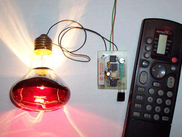
Dim your lighting with your self made PCB and a normal TV remote control.
The meaning from this design is to build it in -i.e. a shaded lamp- and to switch this lamp on and off
the normal way, just like it was switched before the dimmer was build in,
then you could by exception dimming the lamp more or less with your TV remote control.
When you switch the power on there will follow a soft-start till the lamp burns at the previously adjusted dim level.
With the '0' button in TV mode you can dim the lamp, turn more and less bright.
The remote control should send more then one RC5-signal per button-press seeing that the first one is ignored,
this does imply that when the remote button is pressed a short time, there nothing happens.
With the P+ and P- button from a system at choice you can adjust the maximum and minimum dim-levels and
with the '1' button the start-up brightness.
The next time when the 230V power is switched on the lamp starts up at the adjusted dim-level.
Dim your lighting with your self made PCB and a normal TV remote control.
(Re)adjust the dim-levels:
(only necessary when changing the maximum-, minimum- or start-up- level)
First you should select an unused system on your remote control, i.e. SAT, AMP, VCR2 or DCC mode.
Adjust maximum level: Keep, while switching the power on, the P+ button from the remote control pressed and wait until the lamp burns on desired maximum level.
Adjust minimum level: Keep, while switching the power on, the P- button from the remote control pressed and wait until the lamp burns on desired minimum level. Recommended is to adjust the minimum dim level not to "lamp off" level, because then it's easy to forget to switch the power off and use unnecessary power.
Adjust start-up level: Keep, while switching the power on, the '0' button from your remote control pressed and wait until the lamp burns on desired level.
Re-adjust the default values (reset): Keep, while switching the power on, the MUTE button from the remote control pressed.
During adjusting the dim-levels, the dim-level changes slower then normal to make adjusting easier.
When letting the button loose and the adjustment is ok, the red- en green LED blinks for a while.
With the -for the dimmer reserved- system selected on the remote control,
the P+ (dim-level up) / P- (dim-level down) and button '0' (up/down turn by turn) works too.
Button '1' dims directly to the adjusted start-up level.
Which system on the remote control is choosen doesn't matter, the '0' button works always in the TV-mode too.
Above described applies to the here downloadable .BAS and .HEX examples,
but you can ofcourse modify it to your own wishes.
Keep in mind that a remote control does not always send that what you expected.
The volume from TV, SAT, VCR1 and VCR2 are all the same.
Just as the volumegroup from TAPE, TUNER, CD, etc.
And the '0'-'9' buttons from system TAPE for example send nothing at all.
See the lists: RC5 system codes and RC5 command codes
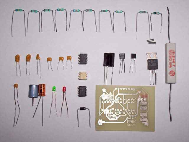
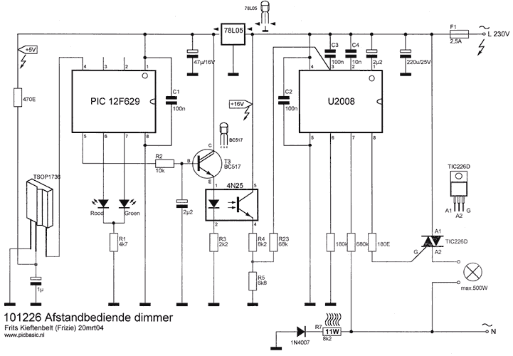
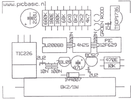
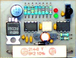
The components, a transformer isn't used here.
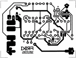
| PCB | 101226 (or etch it self ofcourse) |
| PIC | 12F629 with program 'RC5 dimmer_UK' |
| IC | U2008B |
| Optocoupler | 4N25 |
| Triac | TIC226 |
| LED | Red en green, 3mm |
| IR receiver | TSOP1736 |
| Regulator | 78L05 small voltage regulator (TO-92) |
| Transistor | BC517 don't replace with "just another NPN type" (= NPN darlington) |
| Diode | 1N4007 |
| Resistor | 180E + 470E + 2k2 + 4k7 + 6k8 + 8k2 + 10k + 68k + 180k + 680k |
| Resistor | 11 Watt / 8k2 (do not replace by a 10k type, the circuit shouldn't work!) |
| Capacitor | 10n + 3x 100n + (1µF + 2x 2,2µF tant) + (47µF/16V + 220µF/25V electrolytic, radial) |
Watch out when building this project, seeing that the whole PCB is under life line high voltage!!!
Don't program the PIC in the PCB with --in circuit programming-- !
Seeing that this PCB doesn't use a transformer, the whole PCB is under high 230V network voltage.
The PIC as well!
The 11 Watt resistor can be very warm (60°C), beware for burning or melting materials and bodyparts!
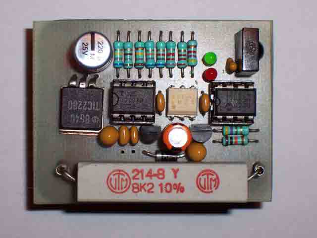
Some parts doesn't fit 100% on this proto-type, but the original PCB is corrected (see bottom photo).
The triac doesn't get warm so the upper metal part can cut off eventually.
The 11 watt resistor becomes pretty hot (60°C is normal in this case).
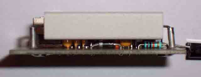
That's why you should solder the resistor with bootlace-ferrules a bit higher on the PCB.
It's important that you bend the two wire's from this resistor on the solderside from the PCB
before you solder it.
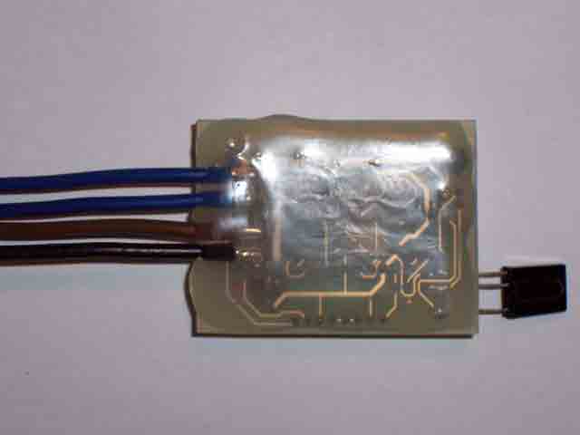
To keep the PCB compact, a big connector is omitted.
The connect-wire's are soldered directly on the PCB's solderside.
Isolate after testing the solderside from the PCB with a hotmelt glue-pistol.
When only the part on the rightside from the optocoupler is build, thus without PIC, 78L05, TSOP1736, etc.
then increase R7 from 8k2 to 22k.
Then it's also possible to change the resistor in a smaller (2W ) type.
| Download RC5_DIM.HEX, V-1 to program in a PIC12F629 | |
| Download RC5_Dimmer_V-1_ UK.bas, the sourcecode for PIC Basic +++ Sourcecode not available (Else look at the Dutch part) +++ |
|
| Download scheme as PDF file | |
| PCB layout 101226 as PDF file | |
| Datasheet U2008.pdf |