 Optional there is a possibility to connect an electronic gong on it.
Click for information about DCF77 on the link underneath:
This project make use of a PIC16F628(A) and a DCF77 receiver from Conrad (Orderno. 64 11 38)
Optional there is a possibility to connect an electronic gong on it.
Click for information about DCF77 on the link underneath:
| The working from the DCF77 time signal |
Connect the output from the DCF77 module with PORTB.0 (pin 6).
The pull-up resistor on the DCF77 output isn't necessary because PORTB.0 internal pull-up is enabled.
Every second is on PORTA.1 (pin 18) a pulse from 0.5 second.
This signal isn't necessary for anything, but maybe you want to connect a LED on it,
so that these wil blink every second, or a piezo buzzer,
so that the clock ticks as an analog clock.
PORTA.0 (pin 17) is the daylight-saving time (DST) pin and is high when it is summer.
For the LCD's 2x20 and 2x24 is it possible to print a W or S on the LCD in winter/summertime.
When connect PORTA.6 (pin 15) to +5V, the clock stays in 24 hours notation and if is choosen for 12 hours notation (AM/PM) then connect this pin with GND.
Use a HD44780 (or compatible) device for the LC-Display.
Download the .HEX file which belongs to the used LCD size.


When searching does take more than 45 seconds, the message "No signal" follows.
The PIC stays searching until it have a decent timesignal reception.

When there is a signal found, it search to the begin from a new minute, this will take maximum 1 minute.
The timebar gives the left time.
If the whole timebar is full, then there is no startsecond found and the message "No signal" appears.

When the startsecond is found, the bits are gonna filled with time and date.
This takes exactly one minute.
If the whole timebar is full, the actual time and date is complete.

From now the day, time and date can be read.

If PORTA.6 (pin 15) is connected to GND the clock stays in 12 hours (AM/PM) notation.
The W stays for Wintertime (S for Summertime, DST).
There is a .HEX file with W / S and a .HEX file without this indication.
When the reception becomes worse or disappears, then also follows the message "No signal".
The PIC still keeps trying to find the actual time back when the reception is good (again).
The basis
If only the time and date must be read from LCD without any fuss then build the circuit from scheme 1.
Adjust the contrast from the LCD with P1.
Scheme 1
Be aware that the DCF77 module (receiver) must have a distance from a working computer to avoid interference,
that means also a distance from minimal 1 metre from the PIC.
Also a lightdimmer at home can make lots of trouble in the DCF77 reception.
A shielded cable isn't necessary, but place on the side from the DCF77 module a serial resistor from 100Ω and
after that a (tantalium) capacitor from 4µ7 over the power supply (see scheme's).
Take if it's possible a cable with 4 conductors,
now there are only 3 necessary but in an other project we use the 4th conductor which is not connected for now.
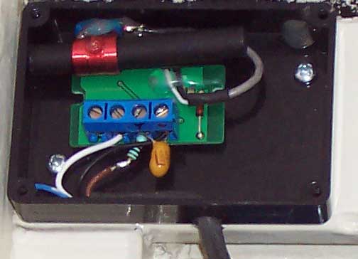 |
| There are two outputs on the DCF77 module, one is direct, the other one is inverted, take the one direct next to the +. The 4th conductor (blue) is for an other new project. |
Program
DCF77 is pretty simple.
Every second (except second 59) comes a pulse from the DCF77 module.
For a 0 is the pulsewidth 0.1 second and for a 1 is this 0.2 second.
To detect the beginning from a new minute, there comes no pulse on the 59th second.
The program measures the time between the pulses and when there is one which takes more than 1 second (no pulse is send out),
the program knows that the next pulse is the first bit from a new minute.
From then all the bits gonna filled in for a new minute.
Every time when there is no pulse on the 59th second (DCF77 protocol),
the program takes care for the '59' on the secondpart on the LCD by itself (See DCF77
info).
Be aware that everything is transmitted in BCD format.
The hours have null-suppression, which means for example that 8 o'clock AM not as 08:00:00 but as 8:00:00 is printed on the LCD.
Paritybits
The program make use of the three transmitted DCF77 paritybits (See DCF77
parity info).
Gong
Real funny is a gong that sounds every half and whole hour.
This happens by making use of the soundgenerator IC SAE800 from Siemens.
This IC is the successor from the old SAB0600.
For those who have at home an old SAB0600, SAB0601 or SAB0602 in stock,
is there a special scheme and PIC program (only with a 2x16 LCD device).
| Scheme and program with a SAB0600, SAB0601 or SAB0602 |
On every whole hour there sounds a 3-tone gong and on the half hours a 2-tone gong.
To activate the gong connect the SAE800 with PORTA.2 (pin 1) and PORTA.3 (pin 2) from the PIC.
Both ports gives every whole hour a short pulse and PORTA.3 also on the half hours.
Ofcourse you can use these pulses also for something else.
When it is dark, the volume from the gong is set automatic to lower level, special for the night's rest from pets.
Hów low the gong sounds depence on the value from R3.
If the LDR is placed in the same room (near to the clock), then the gong sounds
lower when the people are go to bed (when the shaded lamps are switched off).
When no making use from this automatic volume option then connect PORTA.7 to +5V, leave the LDR, P4 and R2, change R3 to 18k and let PORTA.4 (pin 3) open (see scheme 2).
Scheme 2
Adjustment
By connecting PORTB.1 (pin 7) with GND before the power is put on the circuit,
you'll come in testmode 1 and you can adjust the LDR with P4,
how dark it must be before the gong is set to low volume.

Testmode 1
Wait until it becomes dusky and then turn P4 till the LED, connected to PORTA.0 (in normal mode the daylight-saving time indication) goes off.
By connecting PORTB.1 (pin 7) with GND after the power is put on the circuit,
you'll come in testmode 2 which means that the gong gives every minute a 3-tone signal,
so that adjusting the pitch with P2 and the volume with P3 is possible.
By covering the LDR (make it dark,
put a finger on it) you can test the working from the lower gong-volume at the same time.
After adjustment leave PORTB.1 (pin 7) open (internal pull-up).
Those who want no adjustments at all and take the recommended values can
place normal resistors instead of potentiometers:
- replace P2 for a 12k resistor
- replace P3 for a 18k resistor
- replace P4 for a 1M resistor (it must be pretty dark then)
Partly depence these values ofcourse from the used components and speaker.
A speaker from an old transistorradio is fine as long as it has an impedance from 8 - 16Ω.
Check
To verify this home-made DCF77 clock, you can listen to the news-pips on (i.e.BBC) radio every whole hour.
Be aware that not all the news-pips are 100% correct, some stations start the pips in a jingle by hand, not very precise.
Also aware that the reception from the (BBC) radio-news comes direct from air, not by satellite,
because else it looks like that your DCF77 clock runs be fast,
but in reality there is a delay from the (BBC) radio signal.
Another possibility is to compare the clock with another DCF77 clock with seconds hand.
Or use the clock from the website from PTB, see underneath a link, a fast internet connection is
necessary else would the clock from PTB be slow and/or irregular.
Downloads
.HEX files to program in a PIC16F628(A).
Use a LC-Display with HD44780 chip (or compatible).
Download the .HEX file which belongs to your LCD size.
| Download DCF16UKA for LCD 1x16: | 23 Sep '09 12:00 | ||
| Download DCF16UKB for LCD 1x16: | 23 Sep 12:00:00 | ||
| Download DCF16UKE for LCD 1x16: | 23 Sep '09 12:00 | < For display 1x16 which is internal a 2x8 | |
| Download DCF16UKF for LCD 1x16: | 23 Sep 12:00:00 | < For display 1x16 which is internal a 2x8 | |
| Download DCF16UKC for LCD 2x16: |
Wednesday 12:00 23 September '09 |
||
| Download DCF16UKD for LCD 2x16: |
Wed 12:00:00 23 September '09 |
| Download DCF20UKA for LCD 1x20: | Wed 23 Sep 09 12:00 | ||
| Download DCF20UKB for LCD 1x20: | 23 Sep '09 12:00:00 | ||
| Download DCF20UKC for LCD 2x20: |
Wednesday 12:00:00 23 September 2009 |
||
| Download DCF20UKD for LCD 2x20: |
Wednesday 12:00:00 23 September 2009 W |
W / S = DST* |
| Download DCF24UKA for LCD 1x24: | 23 September 2009 12:00 | ||
| Download DCF24UKB for LCD 1x24: | Wed 23 Sep '09 12:00:00 | ||
| Download DCF24UKC for LCD 2x24: |
Wednesday 12:00:00 23 September 2009 |
||
| Download DCF24UKD for LCD 2x24: |
Wednesday 12:00:00 23 September 2009 *W* |
W / S = DST* |